Assembly Guide
This is currently an early draft of the assembly guide. I will keep updating it to add more photographs and tweak the text. If you have any trouble while assembling your Noodle Pi, feel free to email me for assistance. For the Disassembly Guide, scroll down to the bottom of this page.
Update: Here's a video showing the entire assembly process. The video mostly follows the steps listed below, but differs slightly in that Step 5 is done a bit later in the sequence, and Step 11 is broken up into two parts - checking the HyperPixel display, which is done after Step 3, and removing the protective film from the display, which is done just before Step 14. Also, steps 1 and 2 aren't shown in the video.
You should watch the video as well as read the guide completely and carefully before starting assembly. Refer to the notes below for each step before moving forward with that step.
If the video isn't visible above, you can view it here.
Parts List
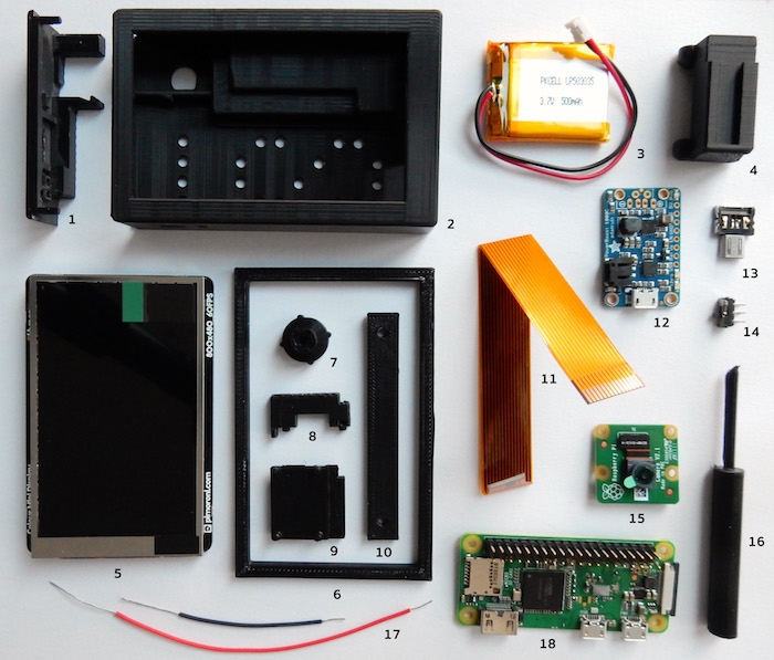
These are all the parts of the Noodle Pi kit. Check that your kit is complete before starting assembly. The numbers in parentheses correspond to the numbers in the image above.
- Noodle Pi shell (2)
- Noodle Pi end cap (1)
- Noodle Pi part A (8)
- Noodle Pi part B (9)
- Pi Zero camera cable (11)
- 2 sets of power wires (Red + Black) (17)
- Switch (14)
- HyperPixel install jig (6)
- Pick (16)
- Focus tool (7)
- Hammer header helper (10)
- USB-OTG adapter (13)
- Noodle Wrist dock (4)
Note: The Noodle Pi kit is shipped with the end cap fitted into the Noodle Pi shell. To separate them, carefully and firmly push up on the left side (as seen from the front) of the end cap from the inside till it pops out.
If you requested the camera board replica which is required to assemble Noodle Pi without a camera, it will already be attached to Part B in your kit. If you need to remove it to replace it with a camera board just carefully detach it from Part B.
These are the third party electronic parts you'll need:
- Raspberry Pi Zero v1.3 or Raspberry Pi Zero W (18)
- Pimoroni Hammer Header (Male) (Attached to Pi Zero - 18)
- Raspberry Pi Camera Board v2.1 (15)
- Pimoroni HyperPixel Display (5)
- Adafruit PowerBoost 1000C (12)
- PKCell 500mAh battery (3)
Overview
Here's an overview of the assembly steps.
- Attach the hammer header to the Raspberry Pi Zero
- Clip the pins of the hammer header
- Connect power wires to PowerBoost
- Connect parts A and B to PowerBoost
- Fit camera on Part B
- Position power wires in HyperPixel display header
- Connect camera cable to Pi Zero
- Insert Pi Zero into HyperPixel header
- Place battery
- Connect battery to PowerBoost
- Check HyperPixel display and remove protective film
- Train battery wires
- Connect camera cable to camera
- Slide components into shell, stage 1
- Attach switch to PowerBoost
- Slide components into shell, stage 2
- Press-fit end cap onto shell
- Boot up
Please be sure to read the details of each step. There are sometimes some tricks to completing a step, which will be highlighted in bold. The details of all the steps are below.
WARNING: The HyperPixel display is super-sensitive! Any excessive pressure or dings to the screen surface will lead to dead pixels and a ruined screen! Be very careful while handling the display and never hold it by the screen surface.
Before starting assembly
You'll need a MicroSD card with Raspbian loaded on it, and the Pimoroni drivers for the HyperPixel display. You can find more details on this here. Preparing the card beforehand is a good idea, as it will require connecting an HDMI screen to your Pi Zero. After the Noodle Pi is assembled you'll need the special HDMI ribbon cable in order to connect it to an HDMI display.
Alternately you can download a customized MicroSD card image for Noodle Pi which already has everything all set up for the HyperPixel display. This can be found here. You'll need 7Zip or Linux's unzip to decompress the ZIP file.
The SHA256 sum of the ZIP file is: f990e65b55d20953ce9b416d200af7ca0be839d4121f307342da6b7656de0add
This image also has a few handy aliases set in
root's .bashrc,
namely reboot-portrait, reboot-landscape,
and reboot-hdmi. These will, respectively, reboot Noodle
Pi into portrait or landscape display mode on the built-in display, or
to use an external HDMI display.
Before starting assembly it's also a good idea to fit your wrist dock (and any other docks you received) onto the shell and remove it a few times. This is because the docks may initially require a bit more force to fit on and remove. After being fitted on and removed a few times, the docks should slide smoothly on and off the Noodle Pi without much pressure required.
Doing this before assembling the Noodle Pi is preferable. After assembly it can become a bit tricky to do while making sure not to damage the screen.
To fit a dock on the Noodle Pi, line up the rail on the back of the Noodle Pi with the groove on the dock. Then slide the dock along the rail till it stops. To remove the dock, press down on the edges of the dock right next to the rail, while holding the Noodle Pi with the end cap facing down.
In some cases, a dock might initially fit extremely tightly and might seem to be stuck. It will eventually loosen up but it may take quite a few docking / undocking cycles to smooth out the docking surfaces (you can also smooth out the docking rail on the Noodle Pi using a file or some 400 grit sandpaper). To remove a dock that seems to be stuck, you can proceed as follows: position the dock at the edge of a solid and stationary counter-top, holding the Noodle Pi with the end-cap on top. Then, while grasping the Noodle Pi in your left hand to catch it as it moves downwards, sharply strike down on the top of the Noodle Pi (on the end-cap) using your right hand. That should dislodge the dock and help get it off the Noodle Pi.
If your Noodle Pi is assembled when you do this, be very careful not to touch the screen during this procedure.
The screen will be facing your left palm as you hold the Noodle Pi in your left hand, so if you hold it firmly and catch it as it moves down the screen shouldn't come into contact with anything. Use a moderate amount of force when you strike down with your right hand, but not an excessive amount.Of course, if your dominant hand is your left hand, you might want to reverse hands when performing this and other procedures described in this guide.
NOTE: While using Noodle Pi with a dock, make sure it is securely locked into place by inserting the USB-OTG adapter into the USB-OTG port. This prevents the Noodle Pi from inadvertently sliding off the dock.
All the docks also have a lanyard hole, so you can attach a wrist strap or other strap to them. It's a good idea to use a wrist strap to secure the Noodle Pi from drops.
Once you've got your dock(s) sliding smoothly on and off the Noodle Pi shell, follow these steps to assemble your Noodle Pi:
Step 1: Attach the hammer header to the Raspberry Pi Zero
If you have a Pi Zero WH with a pre-soldered header, skip ahead to Step 2.
You can attach the hammer header to your Pi Zero as described in the "Fitting hammer headers" guide. Note that the hammer header should be attached to the Pi Zero so the plastic part and longer pins are on the component side of the board.
The acrylic strip that comes with the hammer headers breaks easily when you hammer on it, so you might prefer to use the 3D printed replacement included in the Noodle Pi kit (the "Hammer header helper").
Step 2: Clip the pins of the hammer header
NOTE: Be sure to wear eye protection for this step. The ends of the pins fly off at high speed when clipped.
Clip all the pins on the underside of the Pi Zero board as flush to the board as possible. You can use a "flush cutter" for this, or, in a pinch, a good strong pair of nail clippers.
Step 3: Connect power wires to PowerBoost
This is probably the trickiest step, and it's important to get it right, as correcting mistakes made at this step requires completely disassembling the Noodle Pi. So read through this whole step description first, then take your time and do it carefully to get it right.
After taking the wires out of the plastic bag, check that the ends are tightly twisted and there are no stray strands. If there are stray strands on any of the ends, twist them back tight by holding the insulated end of the wire in your left hand, and twisting the strands clockwise between the thumb and forefinger of your right hand.
To connect each wire to the PowerBoost board, insert the end of the wire which has more insulation stripped off into the hole, from the top (component side) of the board, then cross it uner itself from behind the board. Then, while holding both sides of the wire between thumb and middle finger in your left hand, rotate the PowerBoost board counter-clockwise with your right hand, so the extra length of the exposed wire coils around the wire on the other side. Make sure to coil the extra wire around a stripped section of wire, and not around the insulation.
The red wire goes to the '+' side, black wire to the '-' side.
The wire should be wound tight, but don't over-tighten it. Keep a firm but relaxed grip on the the wire as you turn the board, and stop turning once you feel the wire is wound tight. Over-tightening past that point could cause the wire to break. The kit does include one spare set of wires in case you need them.
After attaching the wires, position them so the wire-wrapped section is directly on top of the hole on the board, as shown below.
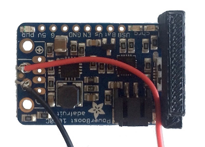
Make sure there are no stray strands. If there are, tuck them in using the pick included in the kit.
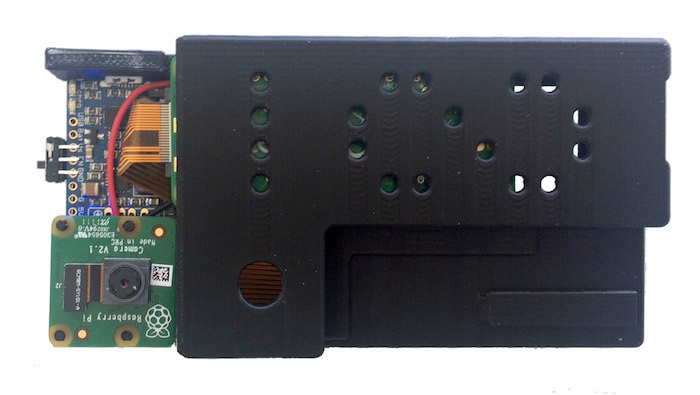
Step 4: Connect parts A and B to PowerBoost
Pull out part A and part B from the little ziplock bag in your kit. Part A goes on the Micro-USB connector side of the PowerBoost, as in the photo above, and part B goes on the other side of the PowerBoost, over the power wires. Make sure that the little pegs on parts A and B are fully inserted into the holes on the PowerBoost board.
Step 5: Fit camera on part B
Now fit the camera onto part B, making sure the 4 little pegs on part B fit into the holes on the camera board. If you're assembling Noodle Pi without a camera, a camera board replica should already be attached to part B in your kit.
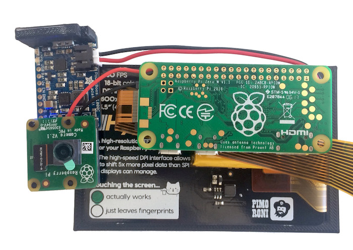
Step 6: Position power wires in HyperPixel display header
Now the free end of each power wire goes into the HyperPixel display header. To begin, remove the HyperPixel display from its packaging and place it face down in the HyperPixel install jig provided in the kit. This is to protect the display, which is super fragile, from damage during the assembly process.
Do not attempt this step without putting the HyperPixel display in the install jig, or you will most certainly damage your display. The HyperPixel display is super fragile and any pressure more than gentle touch on its display surface will lead to dead pixels and a ruined display! Treat it very carefully at all times.
With the HyperPixel display in the install jig and the header at the top right, angle the stripped tips of the power wires at 90 degrees, about 2mm away from the end of the insulation. Make sure the ends of the wires are twisted tight first, with no loose strands. If there are loose strands, twist them tight as described previously. Now insert each tip carefully into the header, in the positions as shown in the photo below.

Keeping the insulation completely off the header, "train" the wires a little till they stay in position and don't try to pop out of the header.
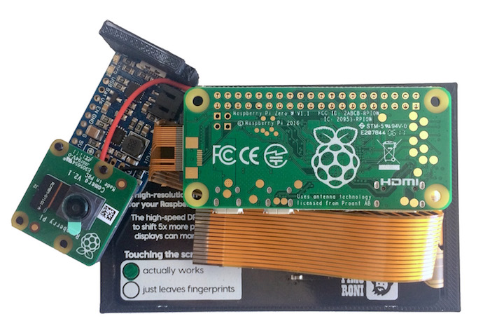
Step 7: Connect camera cable to Pi Zero
Now we're almost ready to connect the Pi Zero to the HyperPixel display. Before doing that though, first connect the camera cable to the Pi Zero. Pull the connector latch out, push in the narrow end of the camera cable, with the shiny connector side facing the non-component side of the Pi Zero, and push the latch back in. The latch is delicate so be careful with it.
Step 8: Insert Pi Zero into HyperPixel header
With the camera cable connected to the Pi Zero, it's now time to connect the Pi Zero to the display. Make sure the power wires are still securely in the header, and then position the Pi Zero over the header, lining up the pins in the correct position. Make sure the pins are properly aligned with the display header on both sides, then firmly and carefully press down on the Pi Zero till the header pins are inserted into the display header. Don't press them down all the way just yet. With the pins inserted halfway, make sure that the insulation of the power wires is out of the way and will not get snagged in between the header edges. You can use the pick to move the wires around till the insulation is clear of the header block. Then press down again on the Pi Zero to fully insert the pins into the header block.
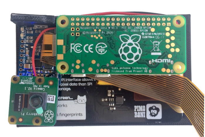
Step 9: Place battery
Place the battery between the screen and the Raspberry Pi Zero, as shown below. Position it so the wired end of it is just clear of the Mini-HDMI connector on the Pi Zero.
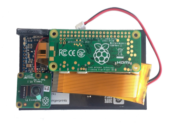
Step 10: Connect battery to PowerBoost
NOTE: Before proceeding further, make sure there is no MicroSD card in the Pi Zero. Once the battery is connected, everything will be powered on, so from this point on be extra careful not to touch any metal or conductive objects to any of the circuit boards.
Go ahead and plug in the battery into the connector on the PowerBoost. The connectors will only mate in one orientation, as shown below.
Step 11: Check HyperPixel display and remove protective film
Carefully lift up the whole assembly, holding it by the edges of the HyperPixel install jig. Peer underneath to have a look at the screen, and check if it is uniformly lit with a low backlight. Check for any streaks that are brighter or darker than the rest of the screen. If you see any such it's likely that your HyperPixel screen is damaged. A small percentage of them seem to arrive damaged out of the box.
If you think your HyperPixel display is damaged you should contact Pimoroni for a replacement. You can still go ahead with the rest of the assembly, though if the screen is damaged there will be dead pixels on the screen.
After checking the display, carefully remove the protective film that covers it. Then place the assembly back down on a tabletop for the next steps, with the HyperPixel display still in the install jig.
Step 12: Train battery wires
Now we want to place the PowerBoost back into place, and tuck the battery wires under the Pi Zero a little bit.
First make sure the battery is positioned so the wired end of it is just clear of the Mini-HDMI connector on the Pi Zero.
Flatten the battery wires and the red power wire coming from the header block along the side of the header. They should run parallel to each other, with the red power wire from the header block on top. The wires should be as straight and flat as possible and not cross over each other.
Use the pick to tuck the excess length of the battery wires into a litte loop under the Pi Zero. You may need to push the camera cable up a little with the pick in order to slide the battery connector under it. Once you get everything back into position as shown below, hold the PowerBoost in place for a little while. This will "train" the battery wires to hold their new shape, so they won't cause the PowerBoost to pop out of place.
Step 13: Connect camera cable to camera
Now connect the camera cable to the camera. To do that you'll need to take the camera board off part B, and pull out the black retaining clip on the camera board connector. Then insert the camera cable into the connector, and carefully push the retaining clip back in, while making sure the cable stays completely inserted into the connector. Finally, fit the camera board back onto part B, making sure the 4 little pegs go into the holes on the camera board.
Step 14: Slide components into shell, stage 1
Now it's time to start fitting the components into the shell.
First, slightly tuck the edge of the upper fold of the camera cable under the HDMI connector. Use your fingers and/or the pick to keep it in that position as you slide the assembly into the shell. That will help it slide in smoothly and not catch on the insides of the shell.
Carefully remove the assembly from the HyerPixel install jig, holding it by the edges of the HyperPixel's circuit board. Be careful not to touch the surface of the screen in the following steps.
With the Noodle Pi shell with the screen side facing down, slowly and carefully slide the assembly into the shell just a little bit (1-2cms). The circuit board of the HyperPixel display should be below the two notches on the sides of the Noodle Pi shell.
Make sure the power wires are all straight and parallel, not crossing over each other, while you slide the assembly into the shell. At all times, make sure not to touch the display surface of the HyperPixel screen.
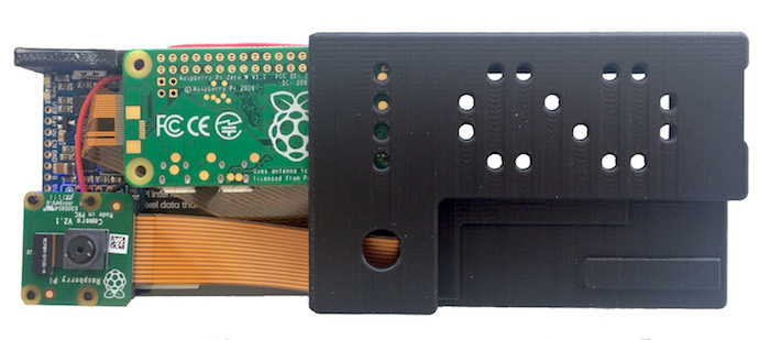
Keep sliding the assembly further into the shell, while making sure that the camera cable also keeps sliding in and doesn't catch. If it does catch, use the pick to adjust its position so you can keep sliding the assembly in smoothly. You want to slide it in to the position as below. If it catches at any point and it isn't due to the camera cable or a crossover of the power cables, gently use a little more force to keep pushing it in. If necessary you can also slide it back out to check for snags in the wires or re-adjust things. Don't use a lot of force at any time. Firm and controlled pressure should do the trick.
Step 15: Attach switch to PowerBoost
With the components partially inserted into the shell as above, now it's time to attach the switch to the PowerBoost. The three pins of the switch go into the PowerBoost board into the three holes marked Vs, EN, GND. Insert the three lower pins of the switch into these holes, from the screen side. Insert them all the way in, then bend them and turn the switch 90 degrees, so it is facing up towards the top of the Noodle Pi, and the three upper pins are now parallel to the board.
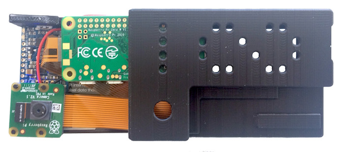
Step 16: Slide components into shell, stage 2
Now slide the components completely into the shell. This is a little tricky, as you have to make sure the camera board aligns with the notch in the shell on one side, and goes under the notch on the back of the shell, while also keeping the PowerBoost properly aligned on the other side.
Everything should go in completely straight. The little pegs on part B should be properly aligned and fitted into the PowerBoost and the camera board. Part A should be vertical and aligned to fit into the shell on its side. Use the focus tool to tighten the camera lens almost to its tightest position (but not all the way - that can make it difficult to loosen it again). Carefully position the camera board so it will slide into the groove on the side of the Noodle Pi shell, as well as under the notch on the back of the shell. To make it slide under the notch on the back of the shell, you may need to press the board a bit towards the front of the Noodle Pi, as you'll see me do with my right index finger at around 14:07 in the assembly video.
Once everything is aligned right, a firm push should get things sliding in further in. Watch out for the camera lens - it might catch on the edge of the shell and need a little help to get sliding into the shell. There's a bit of sticky tape that holds the camera lens to the camera board. This seems to be of different heights on different camera boards, and it gets to be pretty high on some of them. It is compressible, so if your camera lens is sticking out a bit you can press it towards the board and hold it like that to help it slide into the shell.Also watch out for the tiny cable on the camera board, which connects the camera to the board. If the camera moves out of its correct position or orientation on the board, this cable could pop out of the board where it is connected via a tiny connector. If that happens, you'll have to carefully reposition the camera and the cable connector and reconnect the tiny connector back on to the board.
Make sure the assembly of the PowerBoost and the camera board stays horizontal and doesn't tilt up on either side, and continue pushing everything in. Once the camera lens has cleared the edge of the shell and started sliding in, you should be able to push the assembly all the way in till it won't go any further, and the camera should be visible from the camera cutout on the back of the Noodle Pi.
To completely seat the assembly tightly into the shell, firmly press down on the circuit board of the HyperPixel display with the tips of both thumbs, as I do at 14:20 in the assembly video, till it won't move any further in.
Now, looking at the Noodle Pi from the front, slide the switch to the right (OFF) position. The display and all LED lights should turn off.
Step 17: Press-fit end cap onto shell
Now carefully insert the end cap into the end of the shell, and then push it in all the way. It will click into place. Make sure the switch is lined up correctly with its hole in the end cap before you push the end cap in all the way. Pushing it in with the switch misaligned could damage the end cap. The left edge (when looking at the Noodle Pi from the front) of the end cap may be a bit misaligned with the edge of the shell at this point. You can push it in by holding the edge of the end cap against a flat hard surface like the edge of a countertop or table, and using it to apply pressure to the end cap while holding the Noodle Pi at about a 45 degree angle. You may hear another small click as the end cap moves into its correct position.
Congratulations, your Noodle Pi is now fully assembled. Time to:
Step 18: Boot up
Insert the MicroSD card you prepared previously into the MicroSD slot at the bottom of the Noodle Pi, and then turn it on by sliding the switch the the left. A blue LED should turn on on the right of the switch, and your Noodle Pi should boot up in a few seconds.The default screen orientation is landscape mode. I will post details here ASAP on how to use portrait mode.
Disassembly
To disassemble a Noodle Pi, first remove the MicroSD card, and use the focus tool to tighten the camera lens almost all the way in. Pry the end cap up from the left side till it pops loose, then pry up from the right side and remove the end cap. Insert the long stub on the end cap into the opening in the shell for the MicroSD card port, and use it to push on the Pi Zero to start sliding it out of the shell. (You can also use the hammer header helper for this purpose).
Caution: be very careful only to push up on the circuit board and not on the MicroSD card holder which is also right there. If you accidentally push against the MicroSD card holder it will most likely be damaged, rendering the entire Pi Zero useless! So be very careful to position your tool to push only against the circuit board!
You may need to use the pick to pry the camera board out of the shell a little bit, as it may stick and prevent the assembly from sliding out. You may also need to push the camera lens in a bit in order to get it sliding up under the shell. Once the assembly is out a little bit, grasp the HyperPixel circuit board by the edges (be careful not to touch the screen surface), and pull it out more. It should slide out without much trouble. If it sticks you can push up on the Pi Zero a little more via the MicroSD port opening to slide it out more.
Noodle Pi Kit
One Noodle Pi kit, with 3D printed shell and other parts to put together your own Noodle Pi. Note that you will need to purchase the electronic components separately. No soldering required for assembly.
$49 | Add to Cart |
Pre-Assembled Noodle Pi Kit
A full, pre-assembled, tested Noodle Pi complete with all components. With either a Pi Zero v1.3 or a Pi Zero W inside, as you prefer.
$199 | Add to Cart |